07/06/2025 3:44 p.m.
http://cablematic.iskra.cat/en/products/passive-video-transceiver-bnc-dc-to-rj45-ttp111vp-lk-SI012/
http://cablematic.iskra.cat/en/products/passive-video-transceiver-bnc-dc-to-rj45-ttp111vp-lk-SI012/


Passive video transceiver BNC DC to RJ45 TTP111VP-LK
Passive video transceiver BNC DC to RJ45 TTP111VP-LK
REF: SI012


Specifications
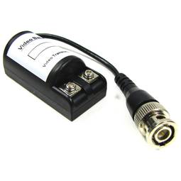
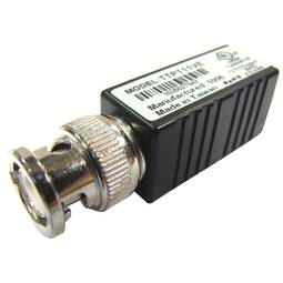
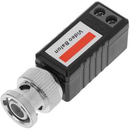
- Video balun and passive video transceiver.
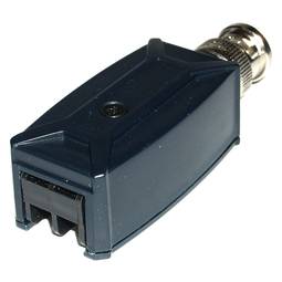
- Small module size: 69 x 25 x 22 mm.
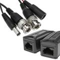
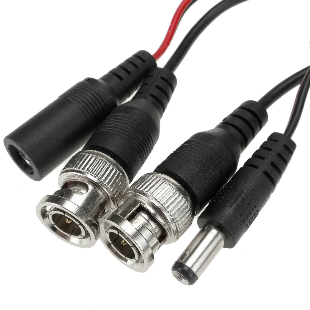
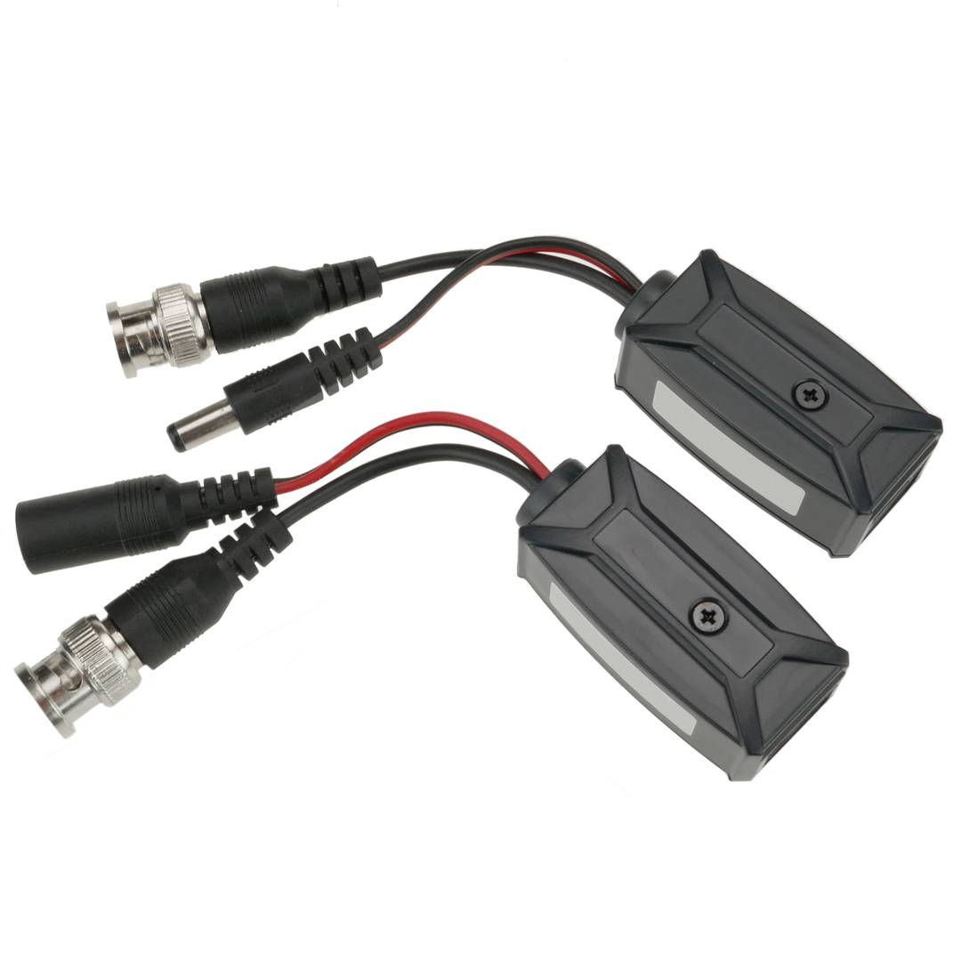
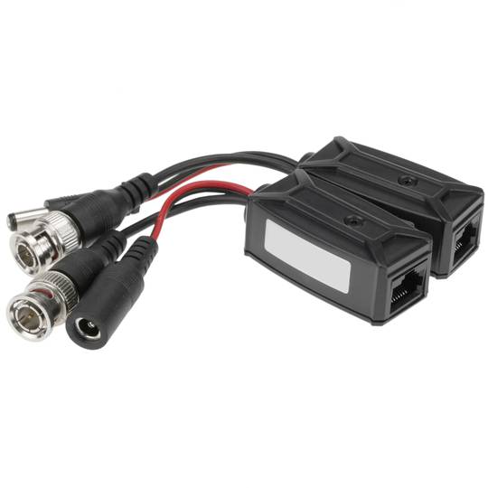
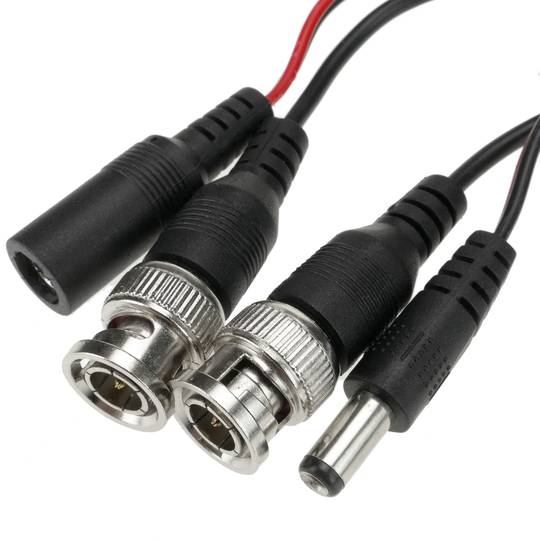
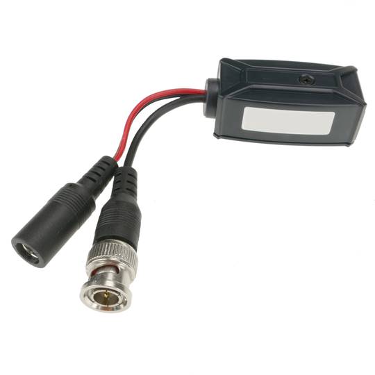
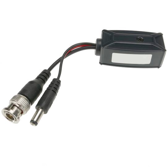
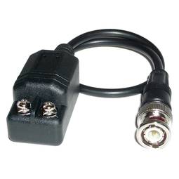
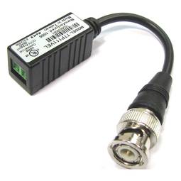
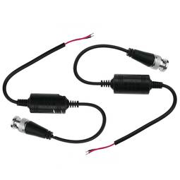
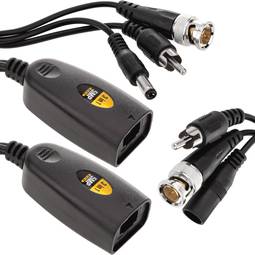
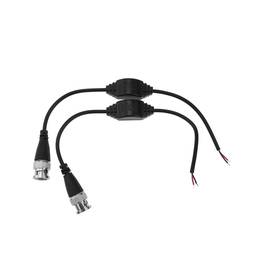
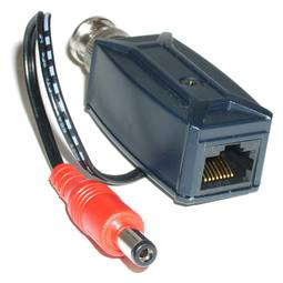
- Camera module: On the side of the camera has a hose that divides into BNC-Male connector and male DC connector for video camera power.
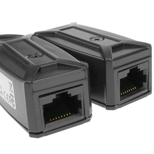
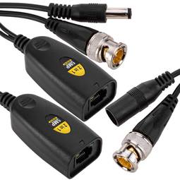
- Video reception module: On the video reception side (DVR or similar) it has a hose that is divided into BNC-Male connector and DC female connector for connection to the power supply that will provide power to the video camera through the UTP cable.
- The video signal coming from the camera and the power supply from the power supply circulates through the UTP cable. With a single UTP cable, the power and the video signal are processed.
PVP
€22.09
Price including VAT:
€27.17
PVD
€18.91
PVP: Retail price.
Check conditions.
PVP: Sale price to distributors.
Check conditions.
warranty
returns
safe
Specifications
- Video balun and passive video transceiver.
- Small module size: 69 x 25 x 22 mm.
- Camera module: On the side of the camera has a hose that divides into BNC-Male connector and male DC connector for video camera power.
- Video reception module: On the video reception side (DVR or similar) it has a hose that is divided into BNC-Male connector and DC female connector for connection to the power supply that will provide power to the video camera through the UTP cable.
- The video signal coming from the camera and the power supply from the power supply circulates through the UTP cable. With a single UTP cable, the power and the video signal are processed.
Related products

Keywords
Did not find what you were looking for? These topic could help you
More info
Transceiver of passive video ( video transceiver ) of composite video (coaxial BNC-Male) and power to twisted pair cable (UTP RJ45-Female). It is a kit that includes two modules (transmitter and receiver). It does the video balun functions. Designed to allow the transmission of video and power signals through twisted pair cable (UTP). Twisted pair cable facilitates installation, is more economical and allows greater transmission distances without loss of quality.
Specifications
Specifications
- Video balun and passive video transceiver.
- Small module size: 69 x 25 x 22 mm.
- Camera module: On the side of the camera has a hose that divides into BNC-Male connector and male DC connector for video camera power.
- Video reception module: On the video reception side (DVR or similar) it has a hose that is divided into BNC-Male connector and DC female connector for connection to the power supply that will provide power to the video camera through the UTP cable.
- The video signal coming from the camera and the power supply from the power supply circulates through the UTP cable. With a single UTP cable, the power and the video signal are processed.
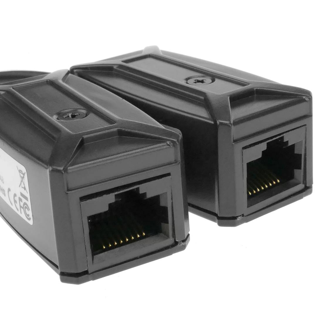
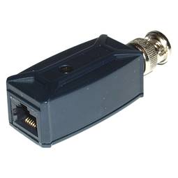
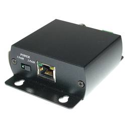
- It is connected to a twisted pair cable and has a RJ45-Female connector.
- Does not require food (passive).
- Transmission range through UTP cable: 400m (color) and 600m (B / N).
- It allows to transmit DC power and video signal (maximum 50m).
- The power is transmitted by 3 pairs of the UTP cable.
- Gross Weight: 120 g
- Product size (width x depth x height): 5.3 x 2.5 x 2.1 cm
- Number of packages: 1
- Packages size: 11.8 x 11.0 x 4.0 cm
- Master-pack: 40
Technical terms
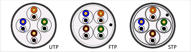
- Types of network cables (UTP, FTP, STP)
- BNC
- DVR
- CVBS
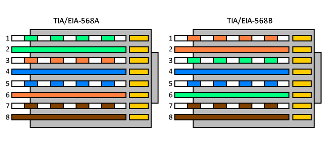
- RJ45
Types of network cables (UTP, FTP, STP)
UTP cable is standard twisted pair is referred by its acronym UTP (Unshiedld Twiested Pair/Unshielded Twisted Pair). The major advantages of this cable are its low cost and ease of handling. Its main disadvantages are a higher error rate compared to other cable types and their limitations to work at high distances without regeneration. FTP is a type of cable caracteriza that each twisted pair is uniformly during creation. A comprehensive screening of all pairs is performed by a apantallante outer sheet. This technique allows to have similar characteristics to the shielded cable. STP is characterized by that each pair is covered with a metal mesh, in the same way that the coaxial cables, and the set of pairs is coated with a sheet apantallante. Referenced frequently with their acronym STP (Shield Twisted Pair/Shielded Twisted Pair)