07/06/2025 7:08 a.m.
http://cablematic.iskra.cat/en/products/telephone-cable-rj11-6p4c-to-rj45-8p4c-1m-RT093/
http://cablematic.iskra.cat/en/products/telephone-cable-rj11-6p4c-to-rj45-8p4c-1m-RT093/
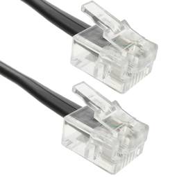
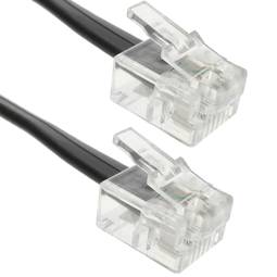
Telephone Cable RJ11 (6P4C) to RJ45 (8p4c) 1m
REF: RT093
Specifications
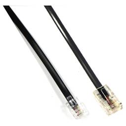
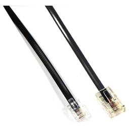
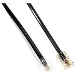
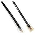
- Telephone cable that allows adapting from RJ11 to RJ45.
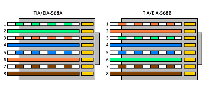
- One end of the cable has an RJ11 connector (6P4C) and the other end of an RJ45 connector (8P4C).
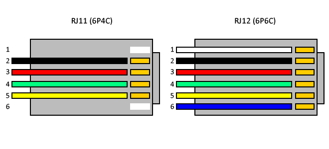
- The 4 central pins of each connector are connected.
- Cable of black color.
- Cable length of 1 m.
PVP
€1.77
Price including VAT:
€2.18
PVD
€1.31
PVP: Retail price.
Check conditions.
PVP: Sale price to distributors.
Check conditions.
warranty
returns
safe
Specifications
- Telephone cable that allows adapting from RJ11 to RJ45.
- One end of the cable has an RJ11 connector (6P4C) and the other end of an RJ45 connector (8P4C).
- The 4 central pins of each connector are connected.
- Cable of black color.
- Cable length of 1 m.
More info
Telephone cable that allows adapting from RJ11 to RJ45. One end of the cable has an RJ11 connector (6P4C) and the other end of an RJ45 connector (8P4C). The 4 central pins of each connector are connected. Cable of black color. Cable length of 1 m.
- Gross Weight: 20 g
- Product size (width x depth x height): 12.0 x 3.0 x 2.0 cm
- Number of packages: 1
- Packages size: 12.0 x 3.0 x 2.0 cm
Technical terms
- RJ11
- RJ45
RJ11
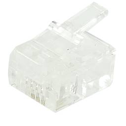
The RJ-11 is mainly used to link telephone networks connector. It is small and has four contacts measures to support 4-way 2 cables. It is the most widely used globally for connecting conventional telephones, which generally tend to use only the two central threads to a single line or a twisted pair connector. And the four wires are used only for telephony equipment special using double line or two telephone pairs. After crimp the cable, it is almost impossible to disarm the RJ-11 without causing its deactivation.
